Mixwell LibraryPlan an oil painting with Leonardo as your teacherTry Mixwell free

Mixwell Library › Leonardo da Vinci › The Notebooks › Part XII

Part XII. Architectural Designs

The Notebooks of Leonardo da Vinci · translated by Jean Paul Richter · § 741 to 769 · 17 plates · public domain · plain text

Richter’s introduction to this part

Introductory Observations on the Architectural Designs (XII), and Writings on Architecture (XIII).

Until now very little has been known regarding Leonardo's labours in the domain of Architecture. No building is known to have been planned and executed by him, though by some contemporary writers incidental allusion is made to his occupying himself with architecture, and his famous letter to Lodovico il Moro,—which has long been a well-known document,—in which he offers his service as an architect to that prince, tends to confirm the belief that he was something more than an amateur of the art. This hypothesis has lately been confirmed by the publication of certain documents, preserved at Milan, showing that Leonardo was not only employed in preparing plans but that he took an active part, with much credit, as member of a commission on public buildings; his name remains linked with the history of the building of the Cathedral at Pavia and that of the Cathedral at Milan.

Leonardo's writings on Architecture are dispersed among a large number of MSS., and it would be scarcely possible to master their contents without the opportunity of arranging, sorting and comparing the whole mass of materials, so as to have some comprehensive idea of the whole. The sketches, when isolated and considered by themselves, might appear to be of but little value; it is not till we understand their general purport, from comparing them with each other, that we can form any just estimate of their true worth.

Leonardo seems to have had a project for writing a complete and separate treatise on Architecture, such as his predecessors and contemporaries had composed—Leon Battista Alberti, Filarete, Francesco di Giorgio and perhaps also Bramante. But, on the other hand, it cannot be denied that possibly no such scheme was connected with the isolated notes and researches, treating on special questions, which are given in this work; that he was merely working at problems in which, for some reason or other he took a special interest.

A great number of important buildings were constructed in Lombardy during the period between 1472 and 1499, and among them there are several by unknown architects, of so high an artistic merit, that it is certainly not improbable that either Bramante or Leonardo da Vinci may have been, directly or indirectly, concerned in their erection.

Having been engaged, for now nearly twenty years, in a thorough study of Bramante's life and labours, I have taken a particular interest in detecting the distinguishing marks of his style as compared with Leonardo's. In 1869 I made researches about the architectural drawings of the latter in the Codex Atlanticus at Milan, for the purpose of finding out, if possible the original plans and sketches of the churches of Santa Maria delle Grazie at Milan, and of the Cathedral at Pavia, which buildings have been supposed to be the work both of Bramante and of Leonardo. Since 1876 I have repeatedly examined Leonardo's architectural studies in the collection of his manuscripts in the Institut de France, and some of these I have already given to the public in my work on "Les Projets Primitifs pour la Basilique de St. Pierre de Rome", P1. 43. In 1879 I had the opportunity of examining the manuscript in the Palazzo Trivulzio at Milan, and in 1880 Dr Richter showed me in London the manuscripts in the possession of Lord Ashburnham, and those in the British Museum. I have thus had opportunities of seeing most of Leonardo's architectural drawings in the original, but of the manuscripts tliemselves I have deciphered only the notes which accompany the sketches. It is to Dr Richter's exertions that we owe the collected texts on Architecture which are now published, and while he has undertaken to be responsible for the correct reading of the original texts, he has also made it his task to extract the whole of the materials from the various MSS. It has been my task to arrange and elucidate the texts under the heads which have been adopted in this work. MS. B. at Paris and the Codex Atlanticus at Milan are the chief sources of our knowledge of Leonardo as an architect, and I have recently subjected these to a thorough re-investigation expressly with a view to this work.

A complete reproduction of all Leonardo's architectural sketches has not, indeed, been possible, but as far as the necessarily restricted limits of the work have allowed, the utmost completeness has been aimed at, and no efforts have been spared to include every thing that can contribute to a knowledge of Leonardo's style. It would have been very interesting, if it had been possible, to give some general account at least of Leonardo's work and studies in engineering, fortification, canal-making and the like, and it is only on mature reflection that we have reluctantly abandoned this idea. Leonardo's occupations in these departments have by no means so close a relation to literary work, in the strict sense of the word as we are fairly justified in attributing to his numerous notes on Architecture.

Leonardo's architectural studies fall naturally under two heads:

I. Those drawings and sketches, often accompanied by short remarks and explanations, which may be regarded as designs for buildings or monuments intended to be built. With these there are occasionally explanatory texts.

II. Theoretical investigations and treatises. A special interest attaches to these because they discuss a variety of questions which are of practical importance to this day. Leonardo's theory as to the origin and progress of cracks in buildings is perhaps to be considered as unique in its way in the literature of Architecture.

HENRY DE GEYMULLER

I. Plans for towns

Richter’s note

A. Sketches for laying out a new town with a double system of high-level and low-level road-ways.

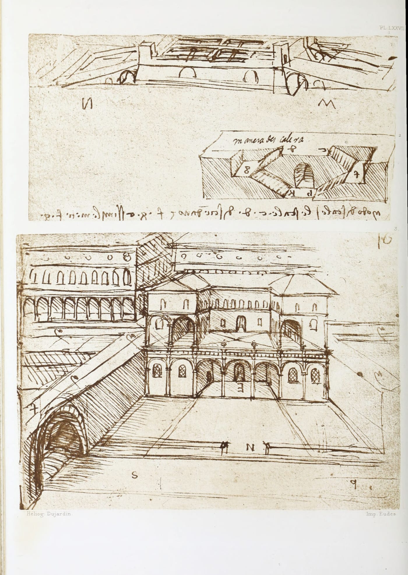
Pl. LXXVII, No. 1 (MS. B, 15b). A general view of a town, with the roads outside it sloping up to the high-level ways within.

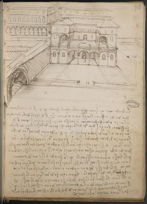
Pl. LXXVII, No. 3 (MS. B, 16b. see No. 741; and MS. B. 15b, see No. 742) gives a partial view of the town, with its streets and houses, with explanatory references.

Pl. LXXVII, No. 2 (MS. B, 15b; see No. 743). View of a double staircaise with two opposite flights of steps.

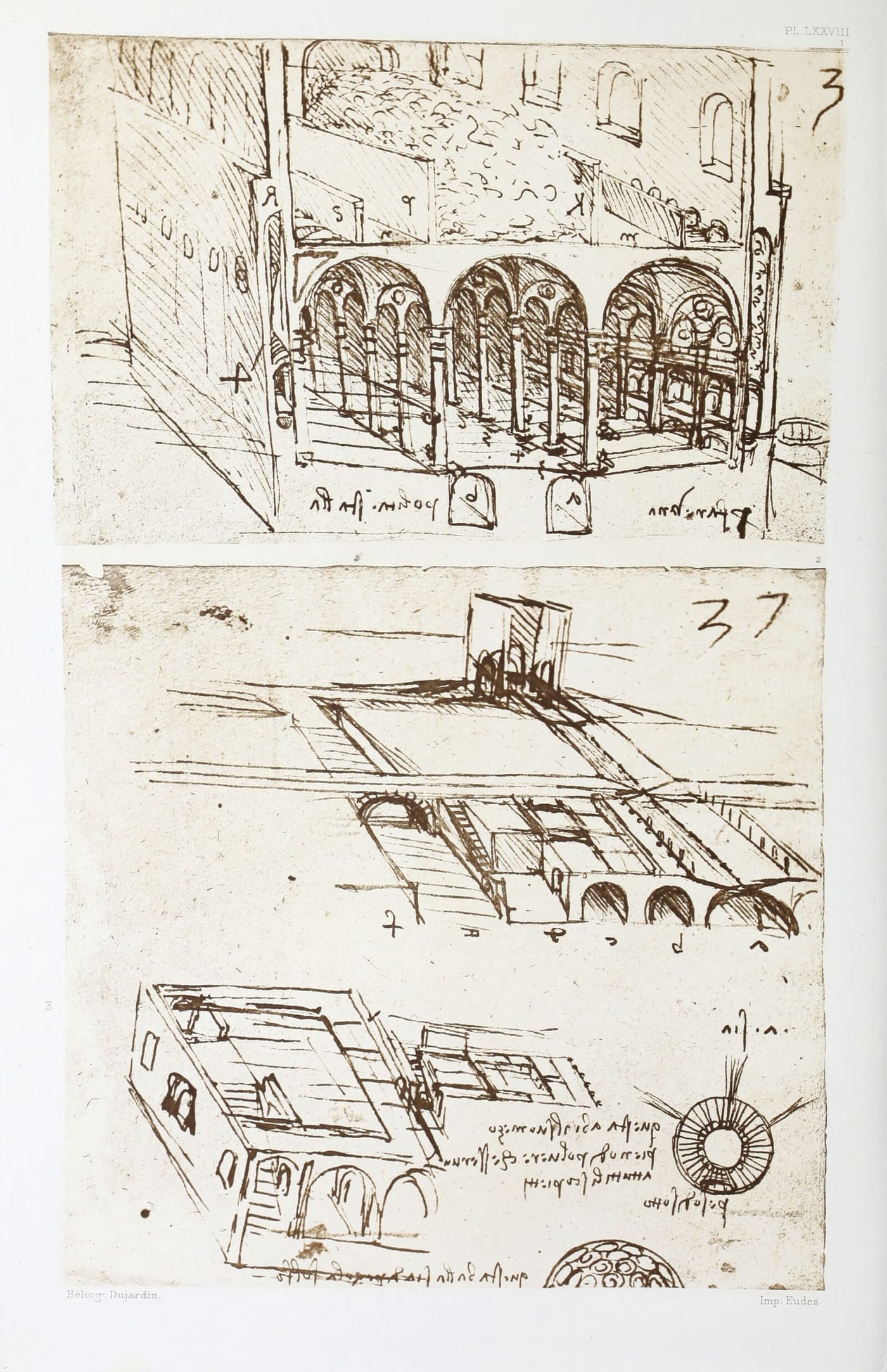
Pl. LXXVIII, Nos. 2 and 3 (MS. B, 37a). Sketches illustrating the connection of the two levels of roads by means of steps. The lower galleries are lighted by openings in the upper roadway.

B. Notes on removing houses (MS. Br. M., 270b, see No. 744).

§ 741
Plate LXXVII: Two Drawings of Plans for Towns; from Manuscript B, Institut de France, Paris—see text Nos. 741, 742 and 743
Plate LXXVII. Two Drawings of Plans for Towns; from Manuscript B, Institut de France, Paris—see text Nos. 741, 742 and 743

The roads m are 6 braccia higher than the roads p s, and each road must be 20 braccia wide and have 1/2 braccio slope from the sides towards the middle; and in the middle let there be at every braccio an opening, one braccio long and one finger wide, where the rain water may run off into hollows made on the same level as p s. And on each side at the extremity of the width of the said road let there be an arcade, 6 braccia broad, on columns; and understand that he who would go through the whole place by the high level streets can use them for this purpose, and he who would go by the low level can do the same. By the high streets no vehicles and similar objects should circulate, but they are exclusively for the use of gentlemen. The carts and burdens for the use and convenience of the inhabitants have to go by the low ones. One house must turn its back to the other, leaving the lower streets between them. Provisions, such as wood, wine and such things are carried in by the doors n, and privies, stables and other fetid matter must be emptied away underground. From one arch to the next

Manuscript page cited by Richter for this passage: Leonardo, Paris Manuscript B, f. 16r, Bibliothèque de l'Institut de France
Manuscript page cited by Richter for this passage: Leonardo, Paris Manuscript B, f. 16r, Bibliothèque de l'Institut de France Source

B. 16a · Pl. LXXVII, No. 3

§ 742

must be 300 braccia, each street receiving its light through the openings of the upper streets, and at each arch must be a winding stair on a circular plan because the corners of square ones are always fouled; they must be wide, and at the first vault there must be a door entering into public privies and the said stairs lead from the upper to the lower streets and the high level streets begin outside the city gates and slope up till at these gates they have attained the height of 6 braccia. Let such a city be built near the sea or a large river in order that the dirt of the city may be carried off by the water.

B. 15b · Pl. LXXVII, No. 3

See Plate LXXVII, shown with § 741

§ 743

The construction of the stairs: The stairs c d go down to f g, and in the same way f g goes down to h k.

B. 15b · Pl. LXXVII, No. 2

See Plate LXXVII, shown with § 741

§ 744

On Moving Houses

Let the houses be moved and arranged in order; and this will be done with facility because such houses are at first made in pieces on the open places, and can then be fitted together with their timbers in the site where they are to be permanent.

Let the men of the country [or the village] partly inhabit the new houses when the court is absent.

Br. M. 270b

II. Plans for canals and streets in a town

Richter’s note

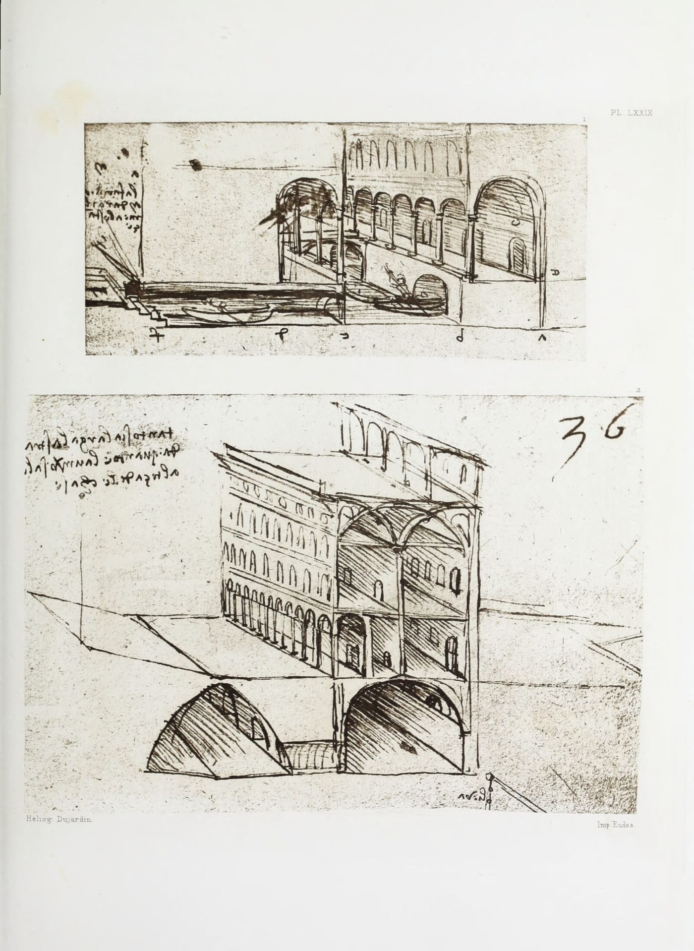
Pl. LXXIX, 1. and 2, (MS. B, 37b, see No. 745, and MS. B. 36a, see No. 746). A Plan for streets and canals inside a town, by which the cellars of the houses are made accessible in boats.

The third text given under No. 747 refers to works executed by Leonardo in France.

§ 745
Plate LXXIX: Two Plans for Canals in a Town; from Manuscript B, Institut de France, Paris—see text Nos. 745 and 746
Plate LXXIX. Two Plans for Canals in a Town; from Manuscript B, Institut de France, Paris—see text Nos. 745 and 746

The front a m will give light to the rooms; a e will be 6 braccia—a b 8 braccia —b e 30 braccia, in order that the rooms under the porticoes may be lighted; c d f is the place where the boats come to the houses to be unloaded. In order to render this arrangement practicable, and in order that the inundation of the rivers may not penetrate into the cellars, it is necessary to chose an appropriate situation, such as a spot near a river which can be diverted into canals in which the level of the water will not vary either by inundations or drought. The construction is shown below; and make choice of a fine river, which the rains do not render muddy, such as the Ticino, the Adda and many others. The construction to oblige the waters to keep constantly at the same level will be a sort of dock, as shown below, situated at the entrance of the town; or better still, some way within, in order that the enemy may not destroy it.

B. 37b · Pl. LXXIX, No. 1

§ 746

Let the width of the streets be equal to the average height of the houses.

B. 36a

See Plate LXXIX, shown with § 745

§ 747

The main underground channel does not receive turbid water, but that water runs in the ditches outside the town with four mills at the entrance and four at the outlet; and this may be done by damming the water above Romorantin.

There should be fountains made in each piazza.

Br. M. 270b

III. Castles and Villas

Richter’s note

A. Castles.

Pl. LXXX, No. 1 (P. V. fol. 39b; No. d'ordre 2282). The fortified place here represented is said by Vallardi to be the "castello" at Milan, but without any satisfactory reason. The high tower behind the "rivellino" ravelin—seems to be intended as a watch-tower.

Pl. LXXX, No. 2 (MS. B, 23b). A similarly constructed tower probably intended for the same use.

Pl. LXXX, No. 3 (MS. B). Sketches for corner towers with steps for a citadel.

Pl. LXXX, No. 4 (W. XVI). A cupola crowning a corner tower; an interesting example of decorative fortification. In this reproduction of the original pen and ink drawing it appears reversed.

B. Projects for Palaces.

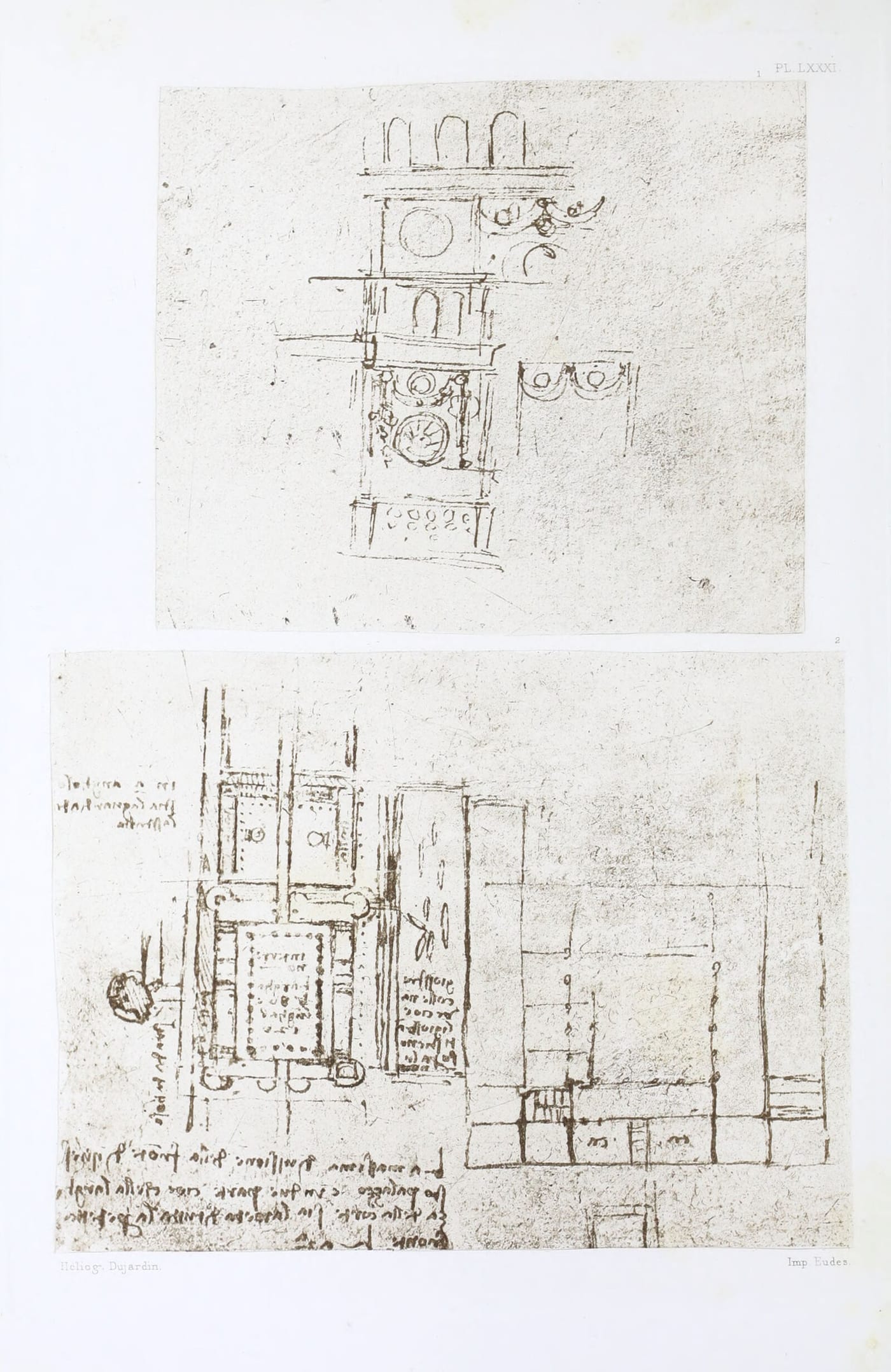
Pl. LXXXI, No. 2 (MS. C. A, 75b; 221a, see No. 748). Project for a royal residence at Amboise in France.

Pl. LXXXII, No. 1 (C. A 308a; 939a). A plan for a somewhat extensive residence, and various details; but there is no text to elucidate it; in courts are written the three names:

Sam cosi giova (St. Mark) (Cosmo) (John), arch mo nino

C. Plans for small castles or Villas.

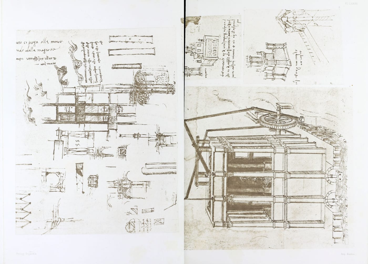
The three following sketches greatly resemble each other. Pl. LXXXII, No. 2 (MS. K3 36b; see No. 749).

Pl. LXXXII, No. 3 (MS. B 60a; See No. 750).

Pl. LXXXIII (W. XVII). The text on this sheet refers to Cyprus (see Topographical Notes No. 1103), but seems to have no direct connection with the sketches inserted between.

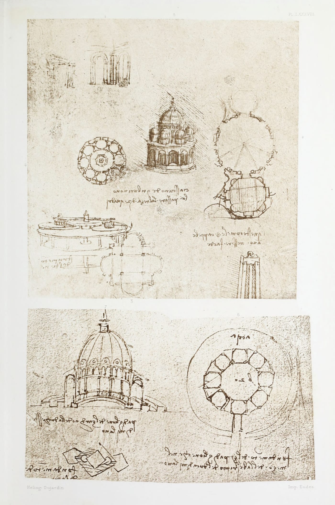
Pl. LXXXVIII, Nos. 6 and 7 (MS. B, 12a; see No. 751). A section of a circular pavilion with the plan of a similar building by the side of it. These two drawings have a special historical interest because the text written below mentions the Duke and Duchess of Milan.

The sketch of a villa on a terrace at the end of a garden occurs in C. A. 150; and in C. A. 77b; 225b is another sketch of a villa somewhat resembling the Belvedere of Pope Innocent VIII, at Rome. In C. A. 62b; 193b there is a Loggia.

Pl. LXXXII, No. 4 (C. A. 387a; 1198a) is a tower-shaped Loggia above a fountain. The machinery is very ingeniously screened from view.

C. Plans for small castles or villas

§ 748
Plate LXXXI: Two Architectural Drawings: No. 1 a sketch for Decorations, from the Trivulzi Manuscript, Milan; No. 2 Plan for a Royal residence; from the Codex Atlanticus, Milan—see text No. 748
Plate LXXXI. Two Architectural Drawings: No. 1 a sketch for Decorations, from the Trivulzi Manuscript, Milan; No. 2 Plan for a Royal residence; from the Codex Atlanticus, Milan—see text No. 748

The Palace of the prince must have a piazza in front of it.

Houses intended for dancing or any kind of jumping or any other movements with a multitude of people, must be on the ground-floor; for I have already witnessed the destruction of some, causing death to many persons, and above all let every wall, be it ever so thin, rest on the ground or on arches with a good foundation.

Let the mezzanines of the dwellings be divided by walls made of very thin bricks, and without wood on account of fire.

Let all the privies have ventilation [by shafts] in the thickness of the walls, so as to exhale by the roofs.

The mezzanines should be vaulted, and the vaults will be stronger in proportion as they are of small size.

The ties of oak must be enclosed in the walls in order to be protected from fire.

The privies must be numerous and going one into the other in order that the stench may not penetrate into the dwellings., and all their doors must shut off themselves with counterpoises.

The main division of the facade of this palace is into two portions; that is to say the width of the court-yard must be half the whole facade; the 2nd ...

C. A. 75b; 221a · Pl. LXXXI, No. 2

§ 749

30 braccia wide on each side; the lower entrance leads into a hall 10 braccia wide and 30 braccia long with 4 recesses each with a chimney.

Plate LXXXII: Four Drawings of projects for Castles and Villas; Nos. 1 and 4 from the Codex Atlanticus, Milan; No. 2 from Manuscript K3—see text No. 749—, and No. 3—see text No. 750—from Manuscript B, Institut de France, Paris
Plate LXXXII. Four Drawings of projects for Castles and Villas; Nos. 1 and 4 from the Codex Atlanticus, Milan; No. 2 from Manuscript K3—see text No. 749—, and No. 3—see text No. 750—from Manuscript B, Institut de France, Paris

K.3 36b · Pl. LXXXII, No. 2 · Pl. LXXXII

§ 751

The pavilion in the garden of the Duchess of Milan.

The plan of the pavilion which is in the middle of the labyrinth of the Duke of Milan.

Plate LXXXVIII: Two Drawings from Manuscript B, Institut de France, Paris: Nos. 1—4 Plans of Churches; Nos. 6, 7 Plan of Pavilion at Milan—see text No. 751
Plate LXXXVIII. Two Drawings from Manuscript B, Institut de France, Paris: Nos. 1—4 Plans of Churches; Nos. 6, 7 Plan of Pavilion at Milan—see text No. 751

B. 12a · Pl. LXXXVIII, Nos. 6 and 7

§ 752

The earth that is dug out from the cellars must be raised on one side so high as to make a terrace garden as high as the level of the hall; but between the earth of the terrace and the wall of the house, leave an interval in order that the damp may not spoil the principal walls.

B. 19b

IV. Ecclesiastical Architecture

Richter’s note

B. The theory of Dome Architecture.

This subject has been more extensively treated by Leonardo in drawings than in writing. Still we may fairly assume that it was his purpose, ultimately to embody the results of his investigation in a "Trattato delle Cupole." The amount of materials is remarkably extensive. MS. B is particularly rich in plans and elevations of churches with one or more domes—from the simplest form to the most complicated that can be imagined. Considering the evident connexion between a great number of these sketches, as well as the impossibility of seeing in them designs or preparatory sketches for any building intended to be erected, the conclusion is obvious that they were not designed for any particular monument, but were theoretical and ideal researches, made in order to obtain a clear understanding of the laws which must govern the construction of a great central dome, with smaller ones grouped round it; and with or without the addition of spires, so that each of these parts by itself and in its juxtaposition to the other parts should produce the grandest possible effect.

In these sketches Leonardo seems to have exhausted every imaginable combination. The results of some of these problems are perhaps not quite satisfactory; still they cannot be considered to give evidence of a want of taste or of any other defect in Leonardo s architectural capacity. They were no doubt intended exclusively for his own instruction, and, before all, as it seems, to illustrate the features or consequences resulting from a given principle.

I have already, in another place, pointed out the law of construction for buildings crowned by a large dome: namely, that such a dome, to produce the greatest effect possible, should rise either from the centre of a Greek cross, or from the centre of a structure of which the plan has some symmetrical affinity to a circle, this circle being at the same time the centre of the whole plan of the building.

Leonardo's sketches show that he was fully aware, as was to be expected, of this truth. Few of them exhibit the form of a Latin cross, and when this is met with, it generally gives evidence of the determination to assign as prominent a part as possible to the dome in the general effect of the building.

While it is evident, on the one hand, that the greater number of these domes had no particular purpose, not being designed for execution, on the other hand several reasons may be found for Leonardo's perseverance in his studies of the subject.

Besides the theoretical interest of the question for Leonardo and his Trattato and besides the taste for domes prevailing at that time, it seems likely that the intended erection of some building of the first importance like the Duomos of Pavia and Como, the church of Sta. Maria delle Grazie at Milan, and the construction of a Dome or central Tower (Tiburio) on the cathedral of Milan, may have stimulated Leonardo to undertake a general and thorough investigation of the subject; whilst Leonardo's intercourse with Bramante for ten years or more, can hardly have remained without influence in this matter. In fact now that some of this great Architect's studies for S. Peter's at Rome have at last become known, he must be considered henceforth as the greatest master of Dome-Architecture that ever existed. His influence, direct or indirect even on a genius like Leonardo seems the more likely, since Leonardo's sketches reveal a style most similar to that of Bramante, whose name indeed, occurs twice in Leonardo's manuscript notes. It must not be forgotten that Leonardo was a Florentine; the characteristic form of the two principal domes of Florence, Sta. Maria del Fiore and the Battisterio, constantly appear as leading features in his sketches.

The church of San Lorenzo at Milan, was at that time still intact. The dome is to this day one of the most wonderful cupolas ever constructed, and with its two smaller domes might well attract the attention and study of a never resting genius such as Leonardo. A whole class of these sketches betray in fact the direct influence of the church of S. Lorenzo, and this also seems to have suggested the plan of Bramante's dome of St. Peter's at Rome.

In the following pages the various sketches for the construction of domes have been classified and discussed from a general point of view. On two sheets: Pl. LXXXIV (C.A. 354b; 118a) and Pl. LXXXV, Nos. 1-11 (Ash. II, 6b) we see various dissimilar types, grouped together; thus these two sheets may be regarded as a sort of nomenclature of the different types, on which we shall now have to treat.

1. Churches formed on the plan of a Greek cross.

Group I.

Domes rising from a circular base.

The simplest type of central building is a circular edifice.

Pl. LXXXIV, No. 9. Plan of a circular building surrounded by a colonnade.

Pl. LXXXIV, No. 8. Elevation of the former, with a conical roof.

Pl. XC. No. 5. A dodecagon, as most nearly approaching the circle.

Pl. LXXXVI, No. 1, 2, 3. Four round chapels are added at the extremities of the two principal axes;—compare this plan with fig. 1 on p. 44 and fig. 3 on p. 47 (W. P. 5b) where the outer wall is octagonal.

Group II.

Domes rising from a square base.

The plan is a square surrounded by a colonnade, and the dome seems to be octagonal.

Pl. LXXXIV. The square plan below the circular building No. 8, and its elevation to the left, above the plan: here the ground-plan is square, the upper storey octagonal. A further development of this type is shown in two sketches C. A. 3a (not reproduced here), and in

Pl. LXXXVI, No. 5 (which possibly belongs to No. 7 on Pl. LXXXIV).

Pl, LXXXV, No. 4, and p. 45, Fig. 3, a Greek cross, repeated p. 45, Fig. 3, is another development of the square central plan.

The remainder of these studies show two different systems; in the first the dome rises from a square plan,—in the second from an octagonal base.

Group III.

Domes rising from a square base and four pillars.

a) First type. A Dome resting on four pillars in the centre of a square edifice, with an apse in the middle, of each of the four sides. We have eleven variations of this type.

aa) Pl. LXXXVIII, No. 3.

bb) Pl. LXXX, No. 5.

cc) Pl. LXXXV, Nos. 2, 3, 5.

dd) Pl. LXXXIV, No. 1 and 4 beneath.

ee) Pl. LXXXV, Nos. 1, 7, 10, 11.

b) Second type. This consists in adding aisles to the whole plan of the first type; columns are placed between the apses and the aisles; the plan thus obtained is very nearly identical with that of S. Lorenzo at Milan.

Fig. 1 on p. 56. (MS. B, 75a) shows the result of this treatment adapted to a peculiar purpose about which we shall have to say a few words later on.

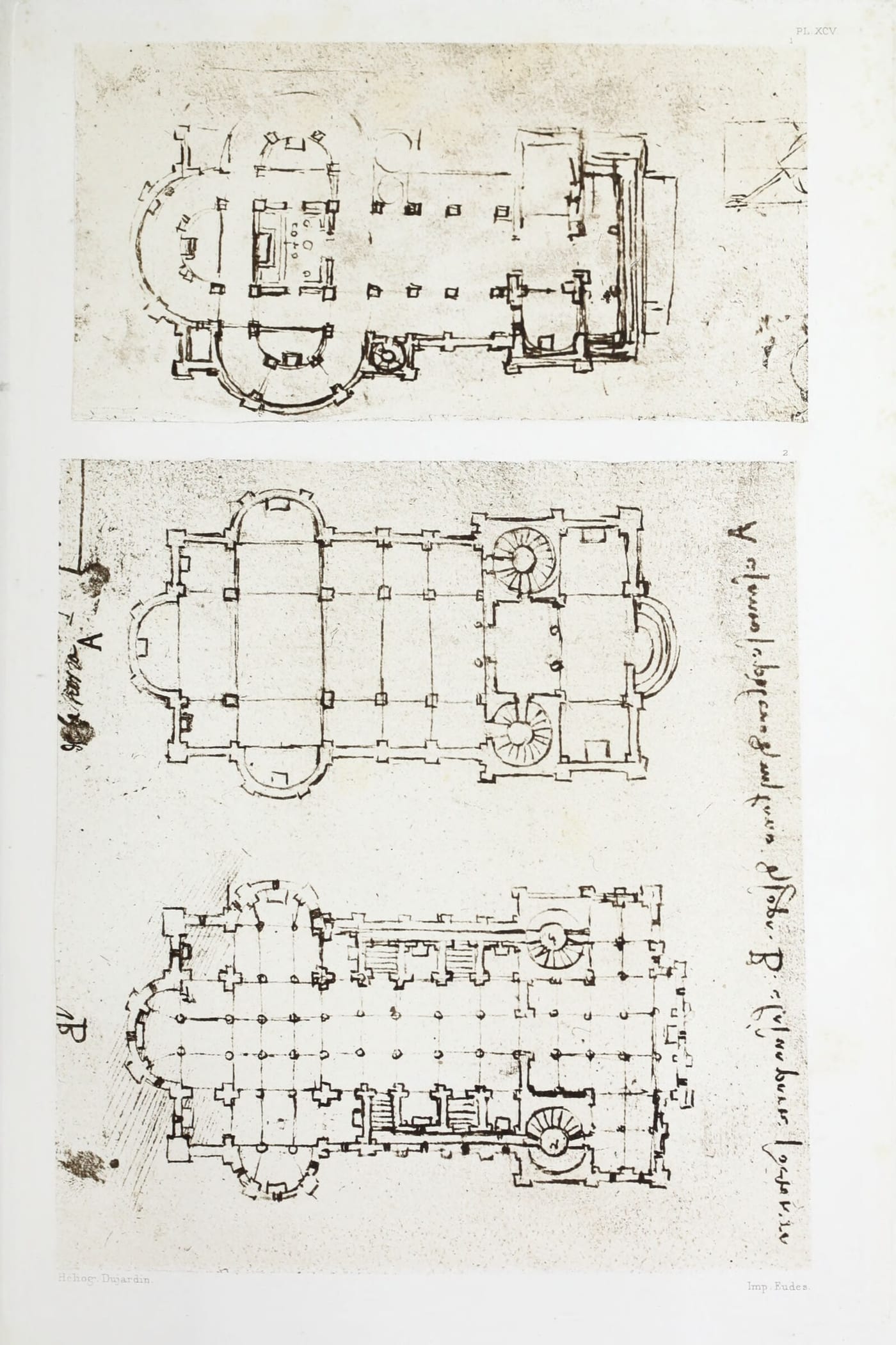
Pl. XCV, No. 1, shows the same plan but with the addition of a short nave. This plan seems to have been suggested by the general arrangement of S. Sepolcro at Milan.

MS. B. 57b (see the sketch reproduced on p.51). By adding towers in the four outer angles to the last named plan, we obtain a plan which bears the general features of Bramante's plans for S. Peter's at Rome. (See p. 51 Fig. 1.)

Group IV.

Domes rising from an octagonal base.

This system, developed according to two different schemes, has given rise to two classes with many varieties.

In a) On each side of the octagon chapels of equal form are added.

In b) The chapels are dissimilar; those which terminate the principal axes being different in form from those which are added on the diagonal sides of the octagon.

a. First Class.

The Chapel "degli Angeli," at Florence, built only to a height of about 20 feet by Brunellesco, may be considered as the prototype of this group; and, indeed it probably suggested it. The fact that we see in MS. B. 11b (Pl. XCIV, No. 3) by the side of Brunellesco's plan for the Basilica of Sto. Spirito at Florence, a plan almost identical with that of the Capella degli Angeli, confirms this supposition. Only two small differences, or we may say improvements, have been introduced by Leonardo. Firstly the back of the chapels contains a third niche, and each angle of the Octagon a folded pilaster like those in Bramante's Sagrestia di S. M. presso San Satiro at Milan, instead of an interval between the two pilasters as seen in the Battistero at Florence and in the Sacristy of Sto. Spirito in the same town and also in the above named chapel by Brunellesco.

The first set of sketches which come under consideration have at first sight the appearance of mere geometrical studies. They seem to have been suggested by the plan given on page 44 Fig. 2 (MS. B, 55a) in the centre of which is written "Santa Maria in perticha da Pavia", at the place marked A on the reproduction.

a) (MS. B, 34b, page 44 Fig. 3). In the middle of each side a column is added, and in the axes of the intercolumnar spaces a second row of columns forms an aisle round the octagon. These are placed at the intersection of a system of semicircles, of which the sixteen columns on the sides of the octagon are the centres.

b) The preceding diagram is completed and becomes more monumental in style in the sketch next to it (MS. B, 35a, see p. 45 Fig. 1). An outer aisle is added by circles, having for radius the distance between the columns in the middle sides of the octagon.

c) (MS. B. 96b, see p. 45 Fig. 2). Octagon with an aisle round it; the angles of both are formed by columns. The outer sides are formed by 8 niches forming chapels. The exterior is likewise octagonal, with the angles corresponding to the centre of each of the interior chapels.

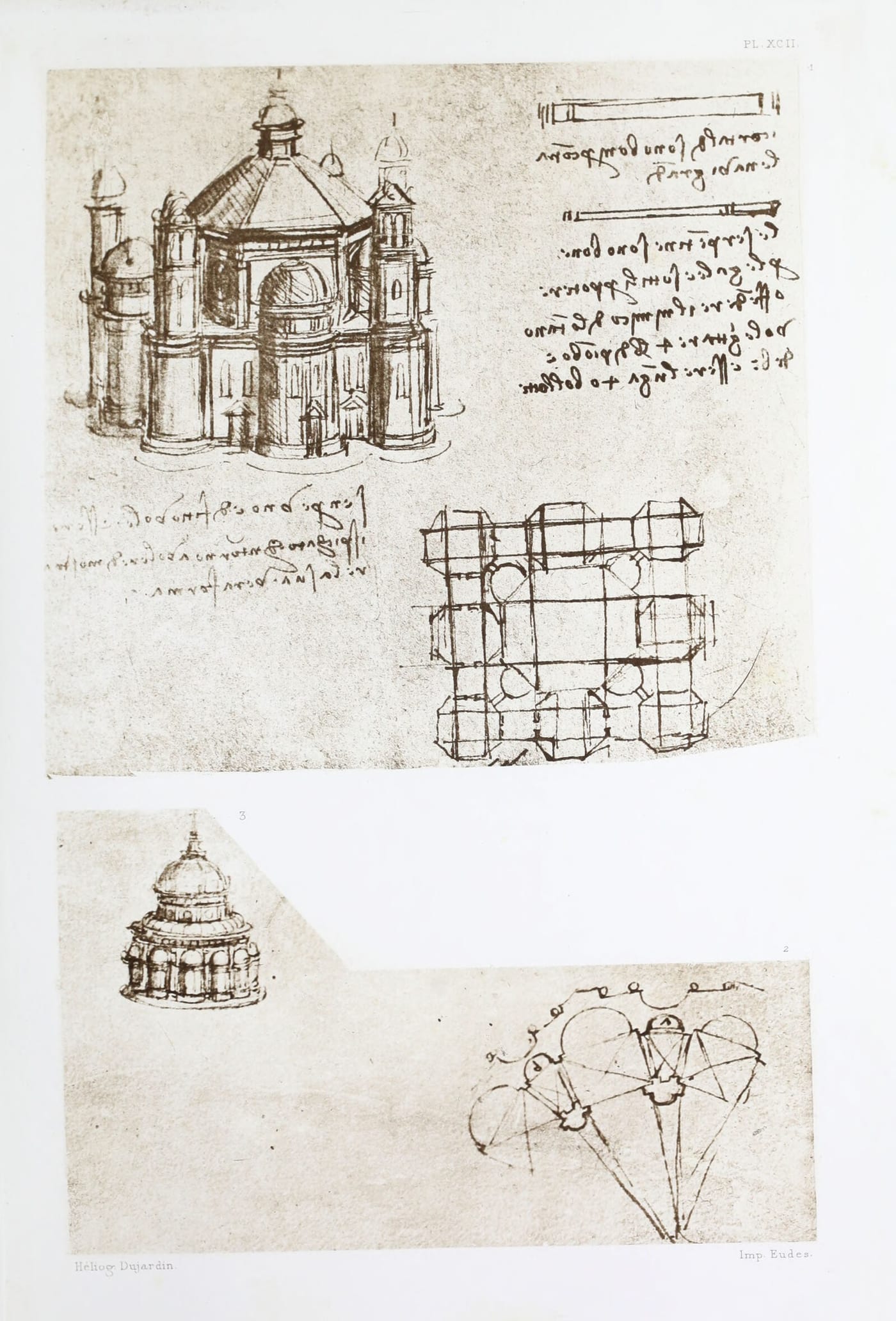
Pl. XCII, No. 2 (MS. B. 96b). Detail and modification of the preceding plan—half columns against piers—an arrangement by which the chapels of the aisle have the same width of opening as the inner arches between the half columns. Underneath this sketch the following note occurs: questo vole - avere 12 facce - co 12 tabernaculi - come - a - b. (This will have twelve sides with twelve tabernacles as a b.) In the remaining sketches of this class the octagon is not formed by columns at the angles.

The simplest type shows a niche in the middle of each side and is repeated on several sheets, viz: MS. B 3; MS. C.A. 354b (see Pl. LXXXIV, No. 11) and MS. Ash II 6b; (see Pl. LXXXV, No. 9 and the elevations No. 8; Pl. XCII, No. 3; MS. B. 4b [not reproduced here] and Pl. LXXXIV, No. 2).

Pl. XCII, 3 (MS. B, 56b) corresponds to a plan like the one in MS. B 35a, in which the niches would be visible outside or, as in the following sketch, with the addition of a niche in the middle of each chapel.

Pl. XC, No. 6. The niches themselves are surrounded by smaller niches (see also No. 1 on the same plate).

Octagon expanded on each side.

A. by a square chapel:

MS. B. 34b (not reproduced here).

B. by a square with 3 niches:

MS. B. 11b (see Pl. XCIV, No. 3).

C. by octagonal chapels:

a) MS. B, 21a; Pl. LXXXVIII, No. 4.

b) No. 2 on the same plate. Underneath there is the remark: "quest'e come le 8 cappele ano a essere facte" (this is how the eight chapels are to be executed).

c) Pl. LXXXVIII, No. 5. Elevation to the plans on the same sheet, it is accompanied by the note: "ciasscuno de' 9 tiburi no'uole -passare l'alteza - di - 2 - quadri" (neither of the 9 domes must exceed the height of two squares).

d) Pl. LXXXVIII, No. 1. Inside of the same octagon. MS. B, 30a, and 34b; these are three repetitions of parts of the same plan with very slight variations.

D. by a circular chapel:

MS. B, 18a (see Fig. 1 on page 47) gives the plan of this arrangement in which the exterior is square on the ground floor with only four of the chapels projecting, as is explained in the next sketch.

Pl. LXXXIX, MS. B, 17b. Elevation to the preceding plan sketched on the opposite side of the sheet, and also marked A. It is accompanied by the following remark, indicating the theoretical character of these studies: questo - edifitio - anchora - starebbe - bene affarlo dalla linja - a - b - c - d - insu. ("This edifice would also produce a good effect if only the part above the lines a b, c d, were executed").

Pl. LXXXIV, No. 11. The exterior has the form of an octagon, but the chapels project partly beyond it. On the left side of the sketch they appear larger than on the right side.

Pl. XC, No. 1, (MS. B, 25b); Repetition of Pl. LXXXIV, No. 11.

Pl. XC, No. 2. Elevation to the plan No. 1, and also to No. 6 of the same sheet.

E. By chapels formed by four niches:

Pl. LXXXIV, No. 7 (the circular plan on the left below) shows this arrangement in which the central dome has become circular inside and might therefore be classed after this group.

The sketch on the right hand side gives most likely the elevation for the last named plan.

F. By chapels of still richer combinations, which necessitate an octagon of larger dimensions:

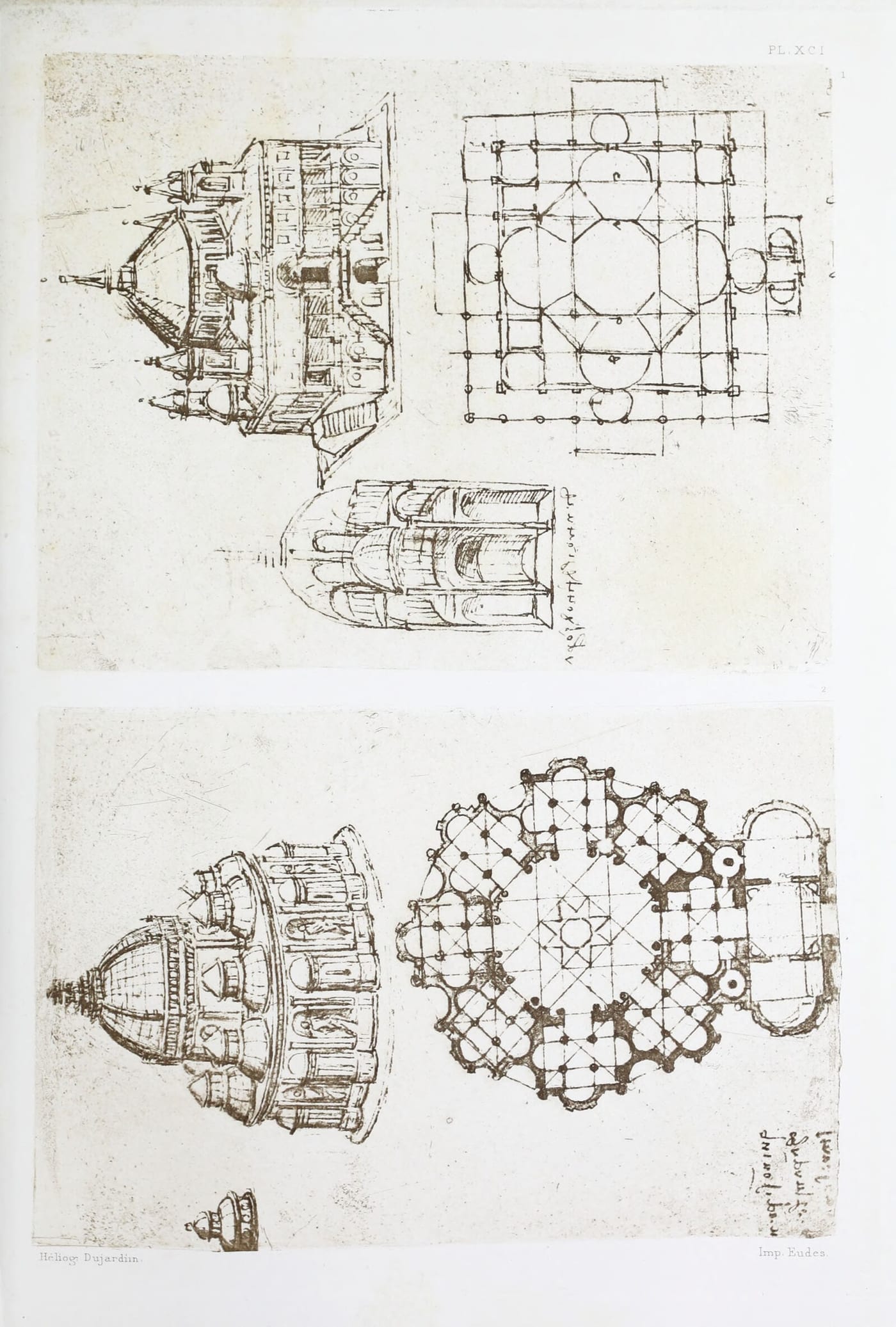
Pl. XCI, No. 2 (MS. Ash. 11. 8b); on this plan the chapels themselves appear to be central buildings formed like the first type of the third group. Pl. LXXXVIII, No. 3.

Pl. XCI, No. 2 above; the exterior of the preceding figure, particularly interesting on account of the alternation of apses and niches, the latter containing statues of a gigantic size, in proportion to the dimension of the niches.

b. Second Class.

Composite plans of this class are generally obtained by combining two types of the first class—the one worked out on the principal axes, the other on the diagonal ones.

MS. B. 22 shows an elementary combination, without any additions on the diagonal axes, but with the dimensions of the squares on the two principal axes exceeding those of the sides of the octagon.

In the drawing W. P. 5b (see page 44 Fig. 1) the exterior only of the edifice is octagonal, the interior being formed by a circular colonnade; round chapels are placed against the four sides of the principal axes.

The elevation, drawn on the same sheet (see page 47 Fig. 3), shows the whole arrangement which is closely related with the one on Pl. LXXXVI No. 1, 2.

MS. B. 21a shows:

a) four sides with rectangular chapels crowned by pediments Pl. LXXXVII No. 3 (plan and elevation);

b) four sides with square chapels crowned by octagonal domes. Pl. LXXXVII No. 4; the plan underneath.

MS. B. 18a shows a variation obtained by replacing the round chapels in the principal axes of the sketch MS. B. l8a by square ones, with an apse. Leonardo repeated both ideas for better comparison side by side, see page 47. Fig. 2.

Pl. LXXXIX (MS. B. 17b). Elevation for the preceding figure. The comparison of the drawing marked M with the plan on page 47 Fig. 2, bearing the same mark, and of the elevation on Pl. LXXXIX below (marked A) with the corresponding plan on page 47 is highly instructive, as illustrating the spirit in which Leonardo pursued these studies.

Pl. LXXXIV No. 12 shows the design Pl. LXXXVII No. 3 combined with apses, with the addition of round chapels on the diagonal sides.

Pl. LXXXIV No. 13 is a variation of the preceding sketch.

Pl. XC No. 3. MS. B. 25b. The round chapels of the preceding sketch are replaced by octagonal chapels, above which rise campaniles.

Pl. XC No. 4 is the elevation for the preceding plan.

Pl. XCII No. 1. (MS. B. 39b.); the plan below. On the principal as well as on the diagonal axes are diagonal chapels, but the latter are separated from the dome by semicircular recesses. The communication between these eight chapels forms a square aisle round the central dome.

Above this figure is the elevation, showing four campaniles on the angles.

Pl. LXXXIV No. 3. On the principal axes are square chapels with three niches; on the diagonals octagonal chapels with niches. Cod. Atl. 340b gives a somewhat similar arrangement.

MS. B. 30. The principal development is thrown on the diagonal axes by square chapels with three niches; on the principal axes are inner recesses communicating with outer ones.

The plan Pl. XCIII No. 2 (MS. B. 22) differs from this only in so far as the outer semicircles have become circular chapels, projecting from the external square as apses; one of them serves as the entrance by a semicircular portico.

The elevation is drawn on the left side of the plan.

MS. B. 19. A further development of MS. B. 18, by employing for the four principal chapels the type Pl. LXXXVIII No. 3, as we have already seen in Pl. XCI No. 2; the exterior presents two varieties.

a) The outer contour follows the inner.

b) It is semicircular.

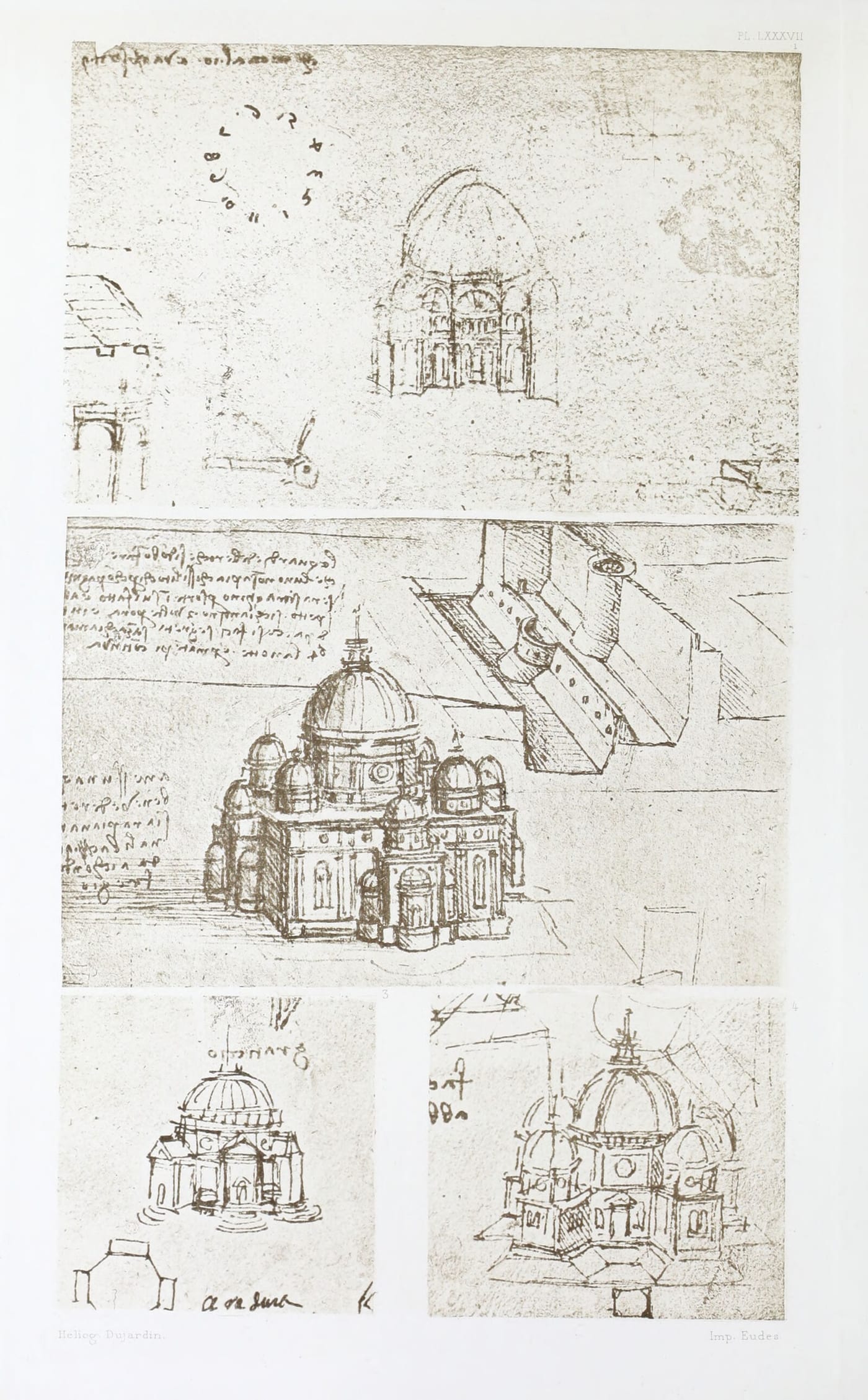
Pl. LXXXVII No. 2 (MS. B. 18b) Elevation to the first variation MS. B. 19. If we were not certain that this sketch was by Leonardo, we might feel tempted to take it as a study by Bramante for St. Peter's at Rome.

MS. P. V. 39b. In the principal axes the chapels of MS. B. 19, and semicircular niches on the diagonals. The exterior of the whole edifice is also an octagon, concealing the form of the interior chapels, but with its angles on their axes.

Group V.

Suggested by San Lorenzo at Milan.

In MS. C. A. 266 IIb, 8l2b there is a plan almost identical with that of San Lorenzo. The diagonal sides of the irregular octagon are not indicated.

If it could be proved that the arches which, in the actual church, exist on these sides in the first story, were added in 1574 by Martimo Bassi, then this plan and the following section would be still nearer the original state of San Lorenzo than at present. A reproduction of this slightly sketched plan has not been possible. It may however be understood from Pl. LXXXVIII No. 3, by suppressing the four pillars corresponding to the apses.

Pl. LXXXVII No. 1 shows the section in elevation corresponding with the above-named plan. The recessed chapels are decorated with large shells in the halfdomes like the arrangement in San Lorenzo, but with proportions like those of Bramante's Sacristy of Santa Maria presso S. Satiro.

MS. C. A. 266; a sheet containing three views of exteriors of Domes. On the same sheet there is a plan similar to the one above-named but with uninterrupted aisles and with the addition of round chapels in the axes (compare Pl. XCVII No. 3 and page 44 Fig. 1), perhaps a reminiscence of the two chapels annexed to San Lorenzo.—Leonardo has here sketched the way of transforming this plan into a Latin cross by means of a nave with side aisles.

Pl. XCI No. 1. Plan showing a type deprived of aisles and comprised in a square building which is surrounded by a portico. It is accompanied by the following text:

Above the plan on the same sheet is a view of the exterior. By the aid of these two figures and the description, sections of the edifice may easily be reconstructed. But the section drawn on the left side of the building seems not to be in keeping with the same plan, notwithstanding the explanatory note written underneath it: "dentro il difitio di sopra" (interior of the edifice above).

Before leaving this group, it is well to remark that the germ of it seems already indicated by the diagonal lines in the plans Pl. LXXXV No. 11 and No. 7. We shall find another application of the same type to the Latin cross in Pl. XCVII No. 3.

2. Churches formed on the plan of a Latin cross.

We find among Leonardo's studies several sketches for churches on the plan of the Latin cross; we shall begin by describing them, and shall add a few observations.

A. Studies after existing Monuments.

Pl. XCIV No. 2. (MS. B. 11b.) Plan of Santo Spirito at Florence, a basilica built after the designs of Brunellesco.—Leonardo has added the indication of a portico in front, either his own invention or the reproduction of a now lost design.

Pl. XCV No. 2. Plan accompanied by the words: "A e santo sepolcro di milano di sopra"(A is the upper church of S. Sepolcro at Milan); although since Leonardo's time considerably spoilt, it is still the same in plan.

The second plan with its note: "B e la sua parte socto tera" (B is its subterranean part [the crypt]) still corresponds with the present state of this part of the church as I have ascertained by visiting the crypt with this plan. Excepting the addition of a few insignificant walls, the state of this interesting part of the church still conforms to Leonardo's sketch; but in the Vestibolo the two columns near the entrance of the winding stairs are absent.

B. Designs or Studies.

PL. XCV No. 1. Plan of a church evidently suggested by that of San Sepolcro at Milan. The central part has been added to on the principle of the second type of Group III. Leonardo has placed the "coro" (choir) in the centre.

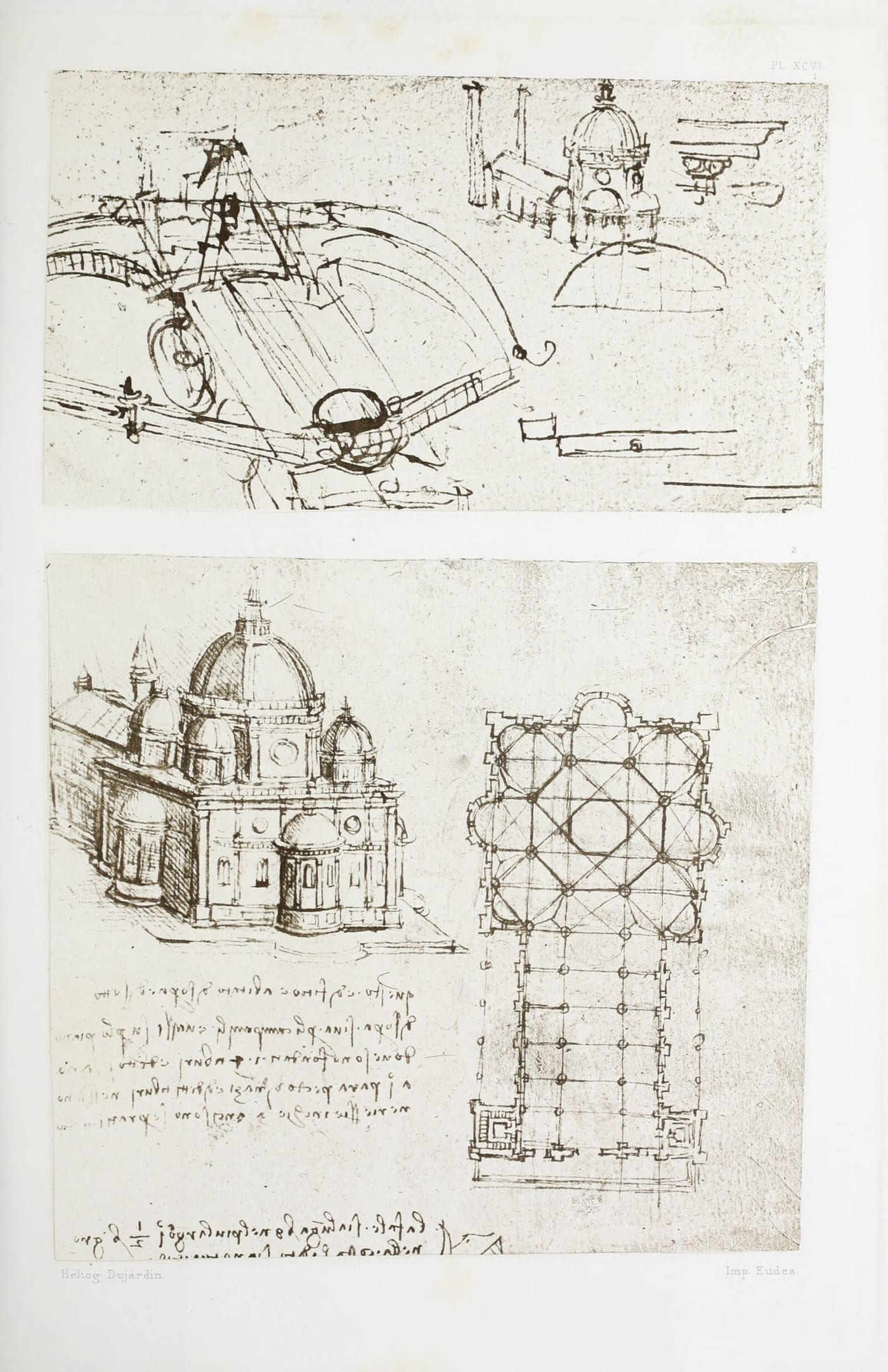
Pl. XCVI No. 2. In the plan the dome, as regards its interior, belongs to the First Class of Group IV, and may be grouped with the one in MS. B. 35a. The nave seems to be a development of the type represented in Pl. XCV No. 2, B. by adding towers and two lateral porticos.

On the left is a view of the exterior of the preceding plan. It is accompanied by the following note:

Pl. XCVI No. 1 (MS. C. A. 16b; 65a). Perspective view of a church seen from behind; this recalls the Duomo at Florence, but with two campaniles.

Pl. XCVII No. 3 (MS. B. 52a). The central part is a development of S. Lorenzo at Milan, such as was executed at the Duomo of Pavia. There is sufficient analogy between the building actually executed and this sketch to suggest a direct connection between them. Leonardo accompanied Francesco di Giorgio when the latter was consulted on June 21st, 1490 as to this church; the fact that the only word accompanying the plan is: "sagrestia", seems to confirm our supposition, for the sacristies were added only in 1492, i. e. four years after the beginning of the Cathedral, which at that time was most likely still sufficiently unfinished to be capable of receiving the form of the present sketch.

Pl. XCVII No. 2 shows the exterior of this design. Below is the note: edifitio al proposito del fodameto figurato di socto (edifice proper for the ground plan figured below).

Here we may also mention the plan of a Latin cross drawn in MS. C. A. fol. 266 (see p. 50).

Pl. XCIV No. 1 (MS. L. 15b). External side view of Brunellesco's Florentine basilica San Lorenzo, seen from the North.

Pl. XCIV No. 4 (V. A. V, 1). Principal front of a nave, most likely of a church on the plan of a Latin cross. We notice here not only the principal features which were employed afterwards in Alberti's front of S. Maria Novella, but even details of a more advanced style, such as we are accustomed to meet with only after the year 1520.

In the background of Leonardo's unfinished picture of St. Jerome (Vatican Gallery) a somewhat similar church front is indicated (see the accompanying sketch).

[Illustration with caption: The view of the front of a temple, apparently a dome in the centre of four corinthian porticos bearing pediments (published by Amoretti Tav. II. B as being by Leonardo), is taken from a drawing, now at the Ambrosian Gallery. We cannot consider this to be by the hand of the master.]

C. Studies for a form of a Church most proper for preaching.

The problem as to what form of church might answer the requirements of acoustics seems to have engaged Leonardo's very particular attention. The designation of "teatro" given to some of these sketches, clearly shows which plan seemed to him most favourable for hearing the preacher's voice.

Pl. XCVII, No. 1 (MS. B, 52). Rectangular edifice divided into three naves with an apse on either side, terminated by a semicircular theatre with rising seats, as in antique buildings. The pulpit is in the centre. Leonardo has written on the left side of the sketch: "teatro da predicare" (Theatre for preaching).

MS. B, 55a (see page 56, Fig. 1). A domed church after the type of Pl. XCV, No. 1, shows four theatres occupying the apses and facing the square "coro" (choir), which is in the centre between the four pillars of the dome. The rising arrangement of the seats is shown in the sketch above. At the place marked B Leonardo wrote teatri per uldire messa (rows of seats to hear mass), at T teatri, and at C coro (choir).

In MS. C.A. 260, are slight sketches of two plans for rectangular choirs and two elevations of the altar and pulpit which seem to be in connection with these plans.

In MS. Ash II, 8a (see p. 56 and 57. Fig. 2 and 3). "Locho dove si predica" (Place for preaching). A most singular plan for a building. The interior is a portion of a sphere, the centre of which is the summit of a column destined to serve as the preacher's pulpit. The inside is somewhat like a modern theatre, whilst the exterior and the galleries and stairs recall the ancient amphitheatres.

[Illustration with caption: Page 57, Fig. 4. A plan accompanying the two preceding drawings. If this gives the complete form Leonardo intended for the edifice, it would have comprised only about two thirds of the circle. Leonardo wrote in the centre "fondamento", a word he often employed for plans, and on the left side of the view of the exterior: locho dove si predicha (a place for preaching in).]

D. Design for a Mausoleum.

Pl. XCVIII (P. V., 182. No. d'ordre 2386). In the midst of a hilly landscape rises an artificial mountain in the form of a gigantic cone, crowned by an imposing temple. At two thirds of the height a terrace is cut out with six doorways forming entrances to galleries, each leading to three sepulchral halls, so constructed as to contain about five hundred funeral urns, disposed in the customary antique style. From two opposite sides steps ascend to the terrace in a single flight and beyond it to the temple above. A large circular opening, like that in the Pantheon, is in the dome above what may be the altar, or perhaps the central monument on the level of the terrace below.

The section of a gallery given in the sketch to the right below shows the roof to be constructed on the principle of superimposed horizontal layers, projecting one beyond the other, and each furnished with a sort of heel, which appears to be undercut, so as to give the appearance of a beam from within. Granite alone would be adequate to the dimensions here given to the key stone, as the thickness of the layers can hardly be considered to be less than a foot. In taking this as the basis of our calculation for the dimensions of the whole construction, the width of the chamber would be about 25 feet but, judging from the number of urns it contains—and there is no reason to suppose that these urns were larger than usual—it would seem to be no more than about 8 or 10 feet.

The construction of the vaults resembles those in the galleries of some etruscan tumuli, for instance the Regulini Galeassi tomb at Cervetri (lately discovered) and also that of the chamber and passages of the pyramid of Cheops and of the treasury of Atreus at Mycenae.

The upper cone displays not only analogies with the monuments mentioned in the note, but also with Etruscan tumuli, such as the Cocumella tomb at Vulci, and the Regulini Galeassi tomb. The whole scheme is one of the most magnificent in the history of Architecture.

It would be difficult to decide as to whether any monument he had seen suggested this idea to Leonardo, but it is worth while to enquire, if any monument, or group of monuments of an earlier date may be supposed to have done so.

E. Studies for the Central Tower, or Tiburio of Milan Cathedral.

Towards the end of the fifteenth century the Fabbricceria del Duomo had to settle on the choice of a model for the crowning and central part of this vast building. We learn from a notice published by G. L. Calvi that among the artists who presented models in the year 1488 were: Bramante, Pietro da Gorgonzola, Luca Paperio (Fancelli), and Leonardo da Vinci.—

Several sketches by Leonardo refer to this important project:

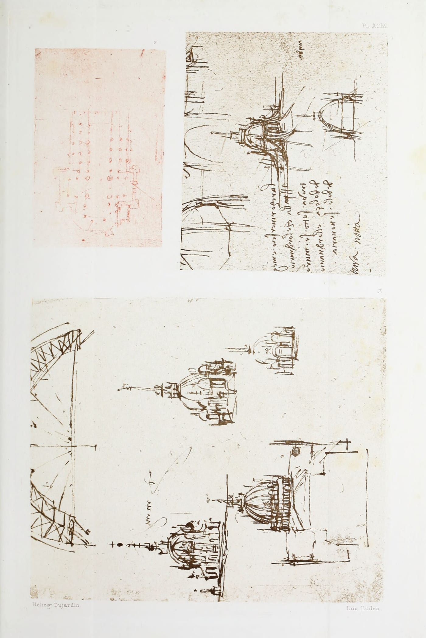
Pl. XCIX, No. 2 (MS. S. K. III, No. 36a) a small plan of the whole edifice.—The projecting chapels in the middle of the transept are wanting here. The nave appears to be shortened and seems to be approached by an inner "vestibolo".—

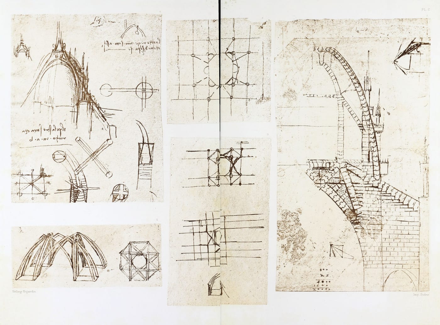
Pl. C, No. 2 (Tr. 21). Plan of the octagon tower, giving the disposition of the buttresses; starting from the eight pillars adjoining the four principal piers and intended to support the eight angles of the Tiburio. These buttresses correspond exactly with those described by Bramante as existing in the model presented by Omodeo.

Pl. C, 3 (MS. Tr. 16). Two plans showing different arrangements of the buttresses, which seem to be formed partly by the intersection of a system of pointed arches such as that seen in Pl. C, No. 5 (MS. B, 27a) destined to give a broader base to the drum. The text underneath is given under No. 788.

MS. B, 3—three slight sketches of plans in connexion with the preceding ones.

Pl. XCIX, No.1 (MS. Tr. 15) contains several small sketches of sections and exterior views of the Dome; some of them show buttress-walls shaped as inverted arches. Respecting these Leonardo notes:

[Figs. 1. and Fig. 2. two sketeches of the dome]

MS. Tr. 9 (see Fig. 1 and 2). Section of the Dome with reverted buttresses between the windows, above which iron anchors or chains seem to be intended. Below is the sketch of the outside.

PI. XCIX, No. 3 (C. A., 262a) four sketches of the exterior of the Dome.

C. A. 12. Section, showing the points of rupture of a gothic vault, in evident connection with the sketches described above.

It deserves to be noticed how easily and apparently without effort, Leonardo manages to combine gothic details and structure with the more modern shape of the Dome.

The following notes are on the same leaf, oni cosa poderosa, and oni cosa poderosa desidera de(scendere); farther below, several multiplications most likely intended to calculate the weight of some parts of the Dome, thus 16 x 47 = 720; 720 x 800 = 176000, next to which is written: peso del pilastro di 9 teste (weight of the pillar 9 diameters high).

Below: 176000 x 8 = 1408000; and below:

Semjlio e se ce 80 (?) il peso del tiburio (six millions six hundred (?) 80 the weight of the Dome).

Bossi hazarded the theory that Leonardo might have been the architect who built the church of Sta. Maria delle Grazie, but there is no evidence to support this, either in documents or in the materials supplied by Leonardos manuscripts and drawings. The sketch given at the side shows the arrangement of the second and third socle on the apses of the choir of that church; and it is remarkable that those sketches, in MS. S. K. M. II2, 2a and Ib, occur with the passage given in Volume I as No. 665 and 666 referring to the composition of the Last Supper in the Refectory of that church.]

F. The Project for lifting up the Battistero of Florence and setting it on a basement.

Among the very few details Vasari gives as to the architectural studies of Leonardo, we read: "And among these models and designs there was one by way of which he showed several times to many ingenious citizens who then governed Florence, his readiness to lift up without ruining it, the church of San Giovanni in Florence (the Battistero, opposite the Duomo) in order to place under it the missing basement with steps; he supported his assertions with reasons so persuasive, that while he spoke the undertaking seemed feasable, although every one of his hearers, when he had departed, could see by himself the impossibility of so vast an undertaking."

In the MS. C. A. fol. 293, there are two sketches which possibly might have a bearing on this bold enterprise. We find there a plan of a circular or polygonal edifice surrounded by semicircular arches in an oblique position. These may be taken for the foundation of the steps and of the new platform. In the perspective elevation the same edifice, forming a polygon, is shown as lifted up and resting on a circle of inverted arches which rest on an other circle of arches in the ordinary position, but so placed that the inverted arches above rest on the spandrels of the lower range.

What seems to confirm the supposition that the lifting up of a building is here in question, is the indication of engines for winding up, such as jacks, and a rack and wheel. As the lifting apparatus represented on this sheet does not seem particularly applicable to an undertaking of such magnitude, we may consider it to be a first sketch or scheme for the engines to be used.
A. General Observations

§ 753

A building should always be detached on all sides so that its form may be seen.

Plate XCII: Two Drawings of Churches; from Manuscript B, Institut de France, Paris—see text No. 753
Plate XCII. Two Drawings of Churches; from Manuscript B, Institut de France, Paris—see text No. 753

B. 39b · Pl. XCII, No. 1

§ 754

Here there cannot and ought not to be any campanile; on the contrary it must stand apart like that of the Cathedral and of San Giovanni at Florence, and of the Cathedral at Pisa, where the campanile is quite detached as well as the dome. Thus each can display its own perfection. If however you wish to join it to the church, make the lantern serve for the campanile as in the church at Chiaravalle.

Plate XCI: Two Drawings of Churches; from the Ashburnham Manuscript II—see text No. 754
Plate XCI. Two Drawings of Churches; from the Ashburnham Manuscript II—see text No. 754

Ash. II. 8b · Pl. XCI

§ 755

It never looks well to see the roofs of a church; they should rather be flat and the water should run off by gutters made in the frieze.

Plate LXXXVII: Four Drawings of Ecclesiastical Architecture: No. 1 from the Codex Atlanticus, Milan; No. 2—see text No. 755—, 3 and 4 from Manuscript B, Institut de France, Paris
Plate LXXXVII. Four Drawings of Ecclesiastical Architecture: No. 1 from the Codex Atlanticus, Milan; No. 2—see text No. 755—, 3 and 4 from Manuscript B, Institut de France, Paris

B. 18b · Pl. LXXXVII, No. 2

§ 756

This edifice is inhabited [accessible] below and above, like San Sepolcro, and it is the same above as below, except that the upper story has the dome c d; and the lower has the dome a b, and when you enter into the crypt, you descend 10 steps, and when you mount into the upper you ascend 20 steps, which, with 1/3 braccio for each, make 10 braccia, and this is the height between one floor of the church and the other.

Ash. II. 7a

See Plate XCI, shown with § 754

B. Designs or Studies

§ 757

This building is inhabited below and above; the way up is by the campaniles, and in going up one has to use the platform, where the drums of the four domes are, and this platform has a parapet in front, and none of these domes communicate with the church, but they are quite separate.

Plate XCV: Two Plans of Churches; from Manuscript B, Institut de France, Paris
Plate XCV. Two Plans of Churches; from Manuscript B, Institut de France, Paris
Plate XCVI: Two Drawings of Churches: No. 7 [sic] from the Codex Atlanticus, Milan; No. 2 from Manuscript B, Institut de France, Paris—see text No. 757
Plate XCVI. Two Drawings of Churches: No. 7 [sic] from the Codex Atlanticus, Milan; No. 2 from Manuscript B, Institut de France, Paris—see text No. 757

B. 24a

E. Studies for the Central tower or Tiburio of Milan Cathedral

§ 758

L'arco rivescio e migliore per fare spalla che l'ordinario, perche il rovescio trova sotto se muro resistete alla sua debolezza, e l'ordinario no trova nel suo debole se non aria

The inverted arch is better for giving a shoulder than the ordinary one, because the former finds below it a wall resisting its weakness, whilst the latter finds in its weak part nothing but air.

Plate XCIX: Three Drawings of Milan Cathedral: No. 1 from the Trivulzio Manuscript, Milan—see text No. 758—; No. 2 in red chalk, from Manuscript III, South Kensington Museum, London; No. 3 from the Codex Atlanticus, Milan
Plate XCIX. Three Drawings of Milan Cathedral: No. 1 from the Trivulzio Manuscript, Milan—see text No. 758—; No. 2 in red chalk, from Manuscript III, South Kensington Museum, London; No. 3 from the Codex Atlanticus, Milan
Plate C: Five Drawings of Milan Cathedral: No. 1 from the Codex Atlanticus, Milan; Nos. 2—4 from the Trivulzio Manuscript, Milan; No. 5 from Manuscript B, Institut de France, Paris
Plate C. Five Drawings of Milan Cathedral: No. 1 from the Codex Atlanticus, Milan; Nos. 2—4 from the Trivulzio Manuscript, Milan; No. 5 from Manuscript B, Institut de France, Paris

Tr. 15 · Pl. C, No. 4 · Pl. C, No. 1 · Tr. 41 · C. A. 303a · MS. C. A. 303b

G. Description of an unknown Temple

§ 759

Twelve flights of steps led up to the great temple, which was eight hundred braccia in circumference and built on an octagonal plan. At the eight corners were eight large plinths, one braccia and a half high, and three wide, and six long at the bottom, with an angle in the middle; on these were eight great pillars, standing on the plinths as a foundation, and twenty four braccia high. And on the top of these were eight capitals three braccia long and six wide, above which were the architrave frieze and cornice, four braccia and a half high, and this was carried on in a straight line from one pillar to the next and so, continuing for eight hundred braccia, surrounded the whole temple, from pillar to pillar. To support this entablature there were ten large columns of the same height as the pillars, three braccia thick above their bases which were one braccia and a half high.

The ascent to this temple was by twelve flights of steps, and the temple was on the twelfth, of an octagonal form, and at each angle rose a large pillar; and between the pillars were placed ten columns of the same height as the pillars, rising at once from the pavement to a height of twenty eight braccia and a half; and at this height the architrave, frieze and cornice were placed which surrounded the temple having a length of eight hundred braccia. At the same height, and within the temple at the same level, and all round the centre of the temple at a distance of 24 braccia farther in, are pillars corresponding to the eight pillars in the angles, and columns corresponding to those placed in the outer spaces. These rise to the same height as the former ones, and over these the continuous architrave returns towards the outer row of pillars and columns.

C. A. 280a; 857a (his margin: C. A. 280a; 852a)

V. Palace architecture

Richter’s note

But a small number of Leonardo's drawings refer to the architecture of palaces, and our knowledge is small as to what style Leonardo might have adopted for such buildings.

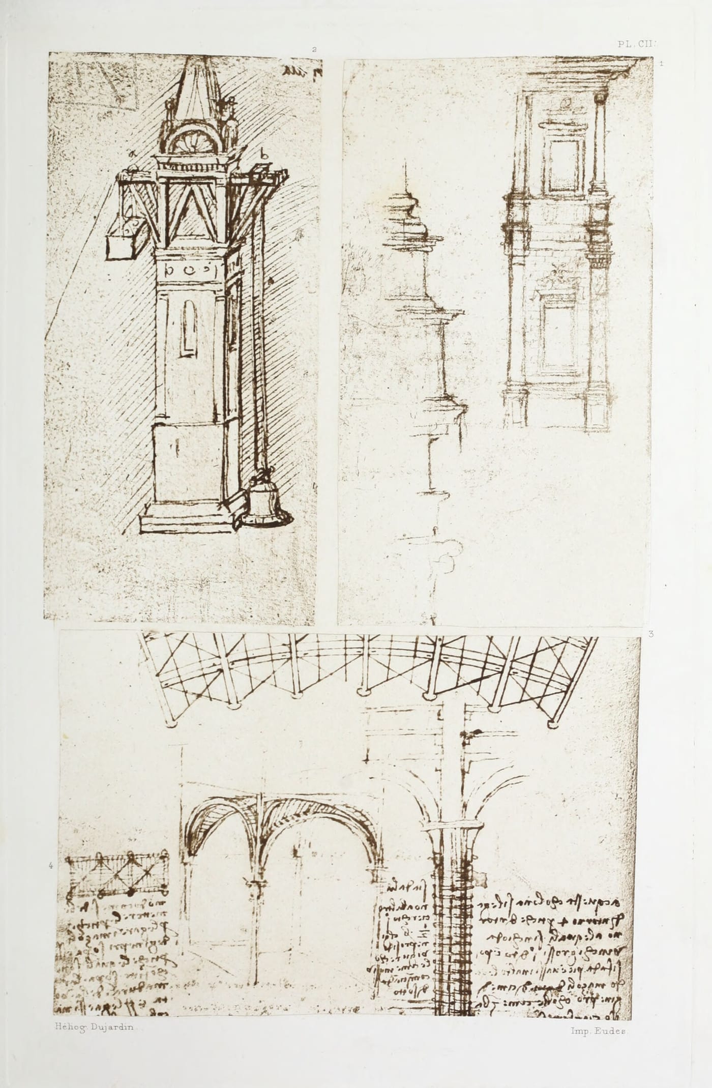
Pl. CII No. 1 (W. XVIII). A small portion of a facade of a palace in two stories, somewhat resembling Alberti's Palazzo Rucellai.—Compare with this Bramante's painted front of the Casa Silvestri, and a painting by Montorfano in San Pietro in Gessate at Milan, third chapel on the left hand side and also with Bramante's palaces at Rome. The pilasters with arabesques, the rustica between them, and the figures over the window may be painted or in sgraffito. The original is drawn in red chalk.

Pl. LXXXI No. 1 (MS. Tr. 42). Sketch of a palace with battlements and decorations, most likely graffiti; the details remind us of those in the Castello at Vigevano.

MS. Mz. 0", contains a design for a palace or house with a loggia in the middle of the first story, over which rises an attic with a Pediment reproduced on page 67. The details drawn close by on the left seem to indicate an arrangement of coupled columns against the wall of a first story.

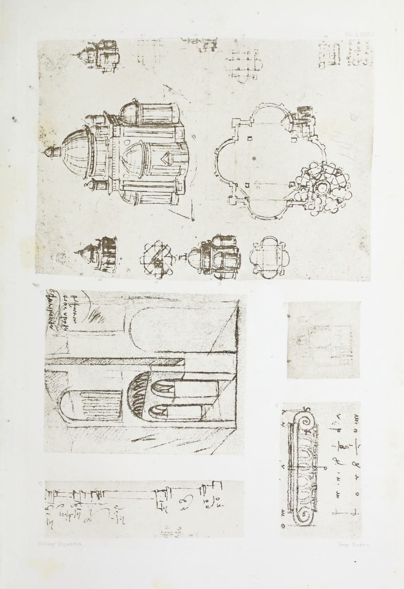
Pl. LXXXV No. 14 (MS. S. K. M. Ill 79a) contains a very slight sketch in red chalk, which most probably is intended to represent the facade of a palace. Inside is the short note 7 he 7 (7 and 7).

MS. J2 8a (see pages 68 Fig. 1 and 2) contains a view of an unknown palace. Its plan is indicated at the side.

In MS. Br. M. 126a(see Fig. 3 on page 68) there is a sketch of a house, on which Leonardo notes; casa con tre terrazi (house with three terraces).

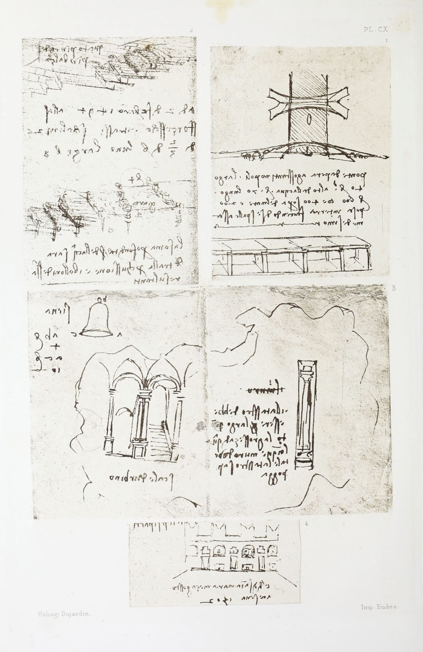
Pl. CX, No. 4 (MS. L. 36b) represents the front of a fortified building drawn at Cesena in 1502 (see No. 1040).

Here we may also mention the singular building in the allegorical composition represented on Pl. LVIII in Vol. I. In front of it appears the head of a sphinx or of a dragon which seems to be carrying the palace away.

The following texts refer to the construction of palaces and other buildings destined for private use:

§ 760

In the courtyard the walls must be half the height of its width, that is if the court be 40 braccia, the house must be 20 high as regards the walls of the said courtyard; and this courtyard must be half as wide as the whole front.

On the dispositions of a stable.

W. XIX · Pl. CI · Pl. LXXXI

See Plate LXXXI, shown with § 748

See Plate CI, shown with § 493

§ 761

For Making a Clean Stable

Plate LXXVIII: Two Architectural Drawings, from Manuscript B, Institut de France, Paris: No. 1 representing a stable—see text No. 761—; No. 2 drawing of Plans for Towns
Plate LXXVIII. Two Architectural Drawings, from Manuscript B, Institut de France, Paris: No. 1 representing a stable—see text No. 761—; No. 2 drawing of Plans for Towns

The manner in which one must arrange a stable. You must first divide its width in 3 parts, its depth matters not; and let these 3 divisions be equal and 6 braccia broad for each part and 10 high, and the middle part shall be for the use of the stablemasters; the 2 side ones for the horses, each of which must be 6 braccia in width and 6 in length, and be half a braccio higher at the head than behind. Let the manger be at 2 braccia from the ground, to the bottom of the rack, 3 braccia, and the top of it 4 braccia. Now, in order to attain to what I promise, that is to make this place, contrary to the general custom, clean and neat: as to the upper part of the stable, i. e. where the hay is, that part must have at its outer end a window 6 braccia high and 6 broad, through which by simple means the hay is brought up to the loft, as is shown by the machine E; and let this be erected in a place 6 braccia wide, and as long as the stable, as seen at k p. The other two parts, which are on either side of this, are again divided; those nearest to the hay-loft are 4 braccia, p s, and only for the use and circulation of the servants belonging to the stable; the other two which reach to the outer walls are 2 braccia, as seen at s k, and these are made for the purpose of giving hay to the mangers, by means of funnels, narrow at the top and wide over the manger, in order that the hay should not choke them. They must be well plastered and clean and are represented at 4 f s. As to the giving the horses water, the troughs must be of stone and above them [cisterns of] water. The mangers may be opened as boxes are uncovered by raising the lids.

Decorations for feasts.

B. 39a · Pl. LXXVIII, No. 1

§ 762

The Way to Construct a Frame-work for Decorating Buildings

The way in which the poles ought to be placed for tying bunches of juniper on to them. These poles must lie close to the framework of the vaulting and tie the bunches on with osier withes, so as to clip them even afterwards with shears.

Let the distance from one circle to another be half a braccia; and the juniper [sprigs] must lie top downwards, beginning from below.

Round this column tie four poles to which willows about as thick as a finger must be nailed and then begin from the bottom and work upwards with bunches of juniper sprigs, the tops downwards, that is upside down.

Plate CII: Three Architectural Drawings: No. 1 in red chalk, from the Royal Library, Windsor Castle; Nos. 2 (reversed) and 3—see text No. 762—from Manuscript B, Institut de France, Pance [sic]
Plate CII. Three Architectural Drawings: No. 1 in red chalk, from the Royal Library, Windsor Castle; Nos. 2 (reversed) and 3—see text No. 762—from Manuscript B, Institut de France, Pance [sic]

B. 28b · Pl. CII, No. 3

VI. Studies of architectural details

Richter’s note

Several of Leonardo's drawings of architectural details prove that, like other great masters of that period, he had devoted his attention to the study of the proportion of such details. As every organic being in nature has its law of construction and growth, these masters endeavoured, each in his way, to discover and prove a law of proportion in architecture. The following notes in Leonardo's manuscripts refer to this subject.

MS. S. K. M. Ill, 47b (see Fig. 1). A diagram, indicating the rules as given by Vitruvius and by Leon Battista Alberti for the proportions of the Attic base of a column.

MS. S. K. M. Ill 55a (see Fig. 2). Diagram showing the same rules.

Pl. LXXXV No. 6 (MS. Ash. II 6b) contains a small sketch of a capital with the following note, written in three lines: I chorni del capitelo deono essere la quarta parte d'uno quadro (The horns of a capital must measure the fourth part of a square).

MS. S. K. M. III 72b contains two sketches of ornamentations of windows.

In MS. C. A. 308a; 938a (see Pl. LXXXII No. 1) there are several sketches of columns. One of the two columns on the right is similar to those employed by Bramante at the Canonica di S. Ambrogio. The same columns appear in the sketch underneath the plan of a castle. There they appear coupled, and in two stories one above the other. The archivolls which seem to spring out of the columns, are shaped like twisted cords, meant perhaps to be twisted branches. The walls between the columns seem to be formed out of blocks of wood, the pedestals are ornamented with a reticulated pattern. From all this we may suppose that Leonardo here had in mind either some festive decoration, or perhaps a pavilion for some hunting place or park. The sketch of columns marked "35" gives an example of columns shaped like candelabra, a form often employed at that time, particularly in Milan, and the surrounding districts for instance in the Cortile di Casa Castiglione now Silvestre, in the cathedral of Como, at Porta della Rana &c.

The Proportions of the stories of a building are indicated by a sketch in MS. S. K. M. II2 11b (see Pl. LXXXV No. 15). The measures are written on the left side, as follows: br 1 1/2–6 3/4—br 1/12–2 br—9 e 1/2–1 1/2—br 5—o 9—o 3 [br=braccia; o=oncie].

Pl. LXXXV No. 13 (MS. B. 62a) and Pl. XCIII No. 1. (MS. B. 15a) give a few examples of arches supported on piers.

§ 764

B toro superiore . . . . . toro superiore 2B nestroli . . . . . . astragali quadre 3B orbiculo . . . . . . . . troclea 4B nestroli . . . . . . astragali quadre 5B toro iferiore . . . . . . toro iferiore 6B latastro . . . . . . . . plintho

S. K. M. III. 48a

§ 765

Steps of Urrbino

The plinth must be as broad as the thickness of the wall against which the plinth is built.

Plate CX: Four Topographical Drawings from Manuscripts in the Institut de France, Paris: No. 1 (Constantinopel)—see text No. 1109—from Manuscript L; No. 2 (Vigevano)—see text No. 1024—in red chalk, from Manuscript H2; No. 3 (Siena, Urbino)—see text Nos. 765 and 1038—and No. 4 (Cesena)—see text No. 1040—from Manuscript L
Plate CX. Four Topographical Drawings from Manuscripts in the Institut de France, Paris: No. 1 (Constantinopel)—see text No. 1109—from Manuscript L; No. 2 (Vigevano)—see text No. 1024—in red chalk, from Manuscript H2; No. 3 (Siena, Urbino)—see text Nos. 765 and 1038—and No. 4 (Cesena)—see text No. 1040—from Manuscript L

L. 19b; 20a · Pl. CX, No. 3

§ 766
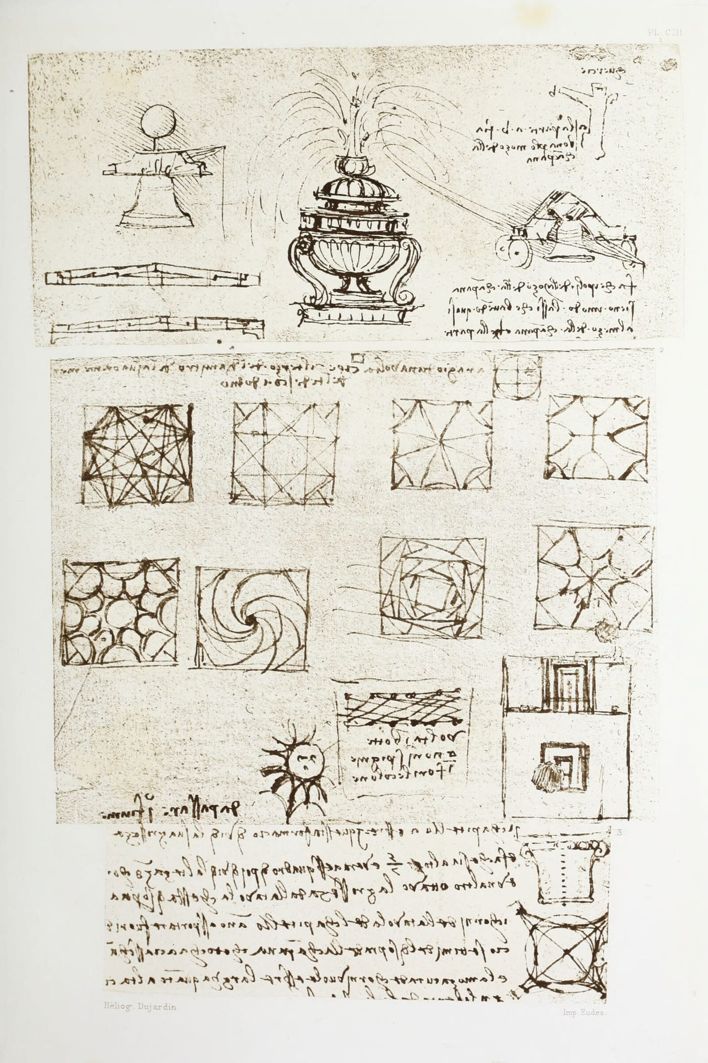
Plate CIII: Three Architectural Drawings: Nos. 1 and 2 from Manuscript B, Institut de France, Paris; No. 3—see text No. 769—(reversed) from the Codex Atlanticus, Milan
Plate CIII. Three Architectural Drawings: Nos. 1 and 2 from Manuscript B, Institut de France, Paris; No. 3—see text No. 769—(reversed) from the Codex Atlanticus, Milan

The ancient architects ...... beginning with the Egyptians (?) who, as Diodorus Siculus writes, were the first to build and construct large cities and castles, public and private buildings of fine form, large and well proportioned .....

The column, which has its thickness at the third part .... The one which would be thinnest in the middle, would break ...; the one which is of equal thickness and of equal strength, is better for the edifice. The second best as to the usefulness will be the one whose greatest thickness is where it joins with the base.

The capital must be formed in this way. Divide its thickness at the top into 8; at the foot make it 5/7, and let it be 5/7 high and you will have a square; afterwards divide the height into 8 parts as you did for the column, and then take 1/8 for the echinus and another eighth for the thickness of the abacus on the top of the capital. The horns of the abacus of the capital have to project beyond the greatest width of the bell 2/7, i. e. sevenths of the top of the bell, so 1/7 falls to the projection of each horn. The truncated part of the horns must be as broad as it is high. I leave the rest, that is the ornaments, to the taste of the sculptors. But to return to the columns and in order to prove the reason of their strength or weakness according to their shape, I say that when the lines starting from the summit of the column and ending at its base and their direction and length ..., their distance apart or width may be equal; I say that this column ...

C. A. 318a; 961a · Pl. CIII, No. 3

§ 767

The cylinder of a body columnar in shape and its two opposite ends are two circles enclosed between parallel lines, and through the centre of the cylinder is a straight line, ending at the centre of these circles, and called by the ancients the axis.

Ash. III. 13b

§ 768

a b is 1/3 of n m; m o is 1/6 of r o. The ovolo projects 1/6 of r o; s 7 1/5 of r o, a b is divided into 9 1/2; the abacus is 3/9 the ovolo 4/9, the bead-moulding and the fillet 2/9 and 1/2.

Plate LXXXV: Five Architectural Drawings: Nos. 1—12 from the Ashburnham Manuscript II; No. 13 from Manuscript I2, and No. 16 from Manuscript H3, Institut de France, Paris—see text No. 768—; Nos. 14—16 (Nos. 14 and 16 in red chalk) from the Manuscripts III and II2, South Kensington Museum, London—see text No. 768
Plate LXXXV. Five Architectural Drawings: Nos. 1—12 from the Ashburnham Manuscript II; No. 13 from Manuscript I2, and No. 16 from Manuscript H3, Institut de France, Paris—see text No. 768—; Nos. 14—16 (Nos. 14 and 16 in red chalk) from the Manuscripts III and II2, South Kensington Museum, London—see text No. 768

H.3 73b · Pl. LXXXV, No. 16

§ 769

Concerning Architraves of One or Several Pieces

An architrave of several pieces is stronger than that of one single piece, if those pieces are placed with their length in the direction of the centre of the world. This is proved because stones have their grain or fibre generated in the contrary direction i. e. in the direction of the opposite horizons of the hemisphere, and this is contrary to fibres of the plants which have ...

Manuscript page cited by Richter for this passage: Leonardo, Paris Manuscript G, f. 52r, Bibliothèque de l'Institut de France
Manuscript page cited by Richter for this passage: Leonardo, Paris Manuscript G, f. 52r, Bibliothèque de l'Institut de France Source

G. 52a

See Plate CIII, shown with § 766